Vérins réglables pour plancher
BTN-L
Les descriptions, dessins et caractéristiques techniques sont présentés directement dans le catalogue 2026 ci-dessous.
Le catalogue et ses données techniques originales sont en anglais.
Demander un devis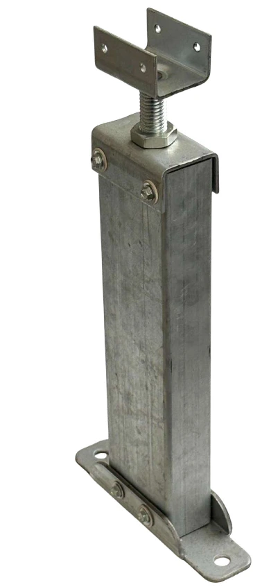
Détails du catalogue original
Page du catalogue 38
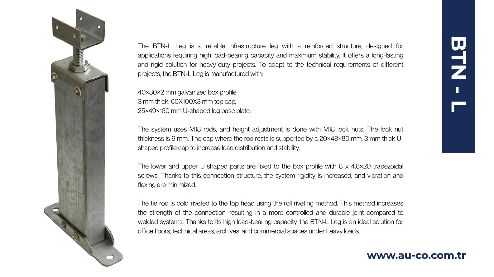
The BTN-L Leg is a reliable infrastructure leg with a reinforced structure, designed for applications requiring high load-bearing capacity and maximum stability. It offers a long-lasting and rigid solution for heavy-duty projects. To adapt to the technical requirements of different projects, the BTN-L Leg is manufactured with: 40×80×2 mm galvanized box profile, 3 mm thick, 60X100X3 mm top cap, 25×49×160 mm U-shaped leg base plate. The system uses M18 rods, and height adjustment is done with M18 lock nuts. The lock nut thickness is 9 mm. The cap where the rod rests is supported by a 20×48×80 mm, 3 mm thick U- shaped profile cap to increase load distribution and stability. The lower and upper U-shaped parts are fixed to the box profile with 8 x 4.8×20 trapezoidal screws. Thanks to this connection structure, the system rigidity is increased, and vibration and flexing are minimized. The tie rod is cold-riveted to the top head using the roll riveting method. This method increases the strength of the connection, resulting in a more controlled and durable joint compared to welded systems. Thanks to its high load-bearing capacity, the BTN-L Leg is an ideal solution for office floors, technical areas, archives, and commercial spaces under heavy loads. BTN - L
L’ordre de lecture du texte peut différer de celui de la page originale en colonnes.
Page du catalogue 39
Technical Data: Element class according to DIN EN 12825: 6 Single Load: ≥ 12 kN Distributed Load: ≥ 45 kN Breaking Load: ≥ 49 kN Head: Head plate dimensions: 60 × 100 × 3 mm U-shaped head is mounted by rolling with M18 rod Height adjustment can be made with M18 lock nut Lockle nut thickness is 9 mm U-shaped head is designed for 40×40 – 40×60 – 40×80 mm profiles Mounting is done to the profile in the channel through the holes on the head with 4.8×20 mm trapezoidal screws. Base and Rod: Foot BODY: 40 × 80 × 2 mm galvanized box profile Rod head: 20 × 48 × 80 mm, U-shaped, 3 mm thick profile cover Foot base sheet: 25 × 49 × 160 mm U-shaped sheet metal Adjustment and Fixing: The lower and upper U-shaped parts are fixed to the box profile with 8 trapezoidal screws of 4.8 × 20 mm. After the appropriate height adjustment, the adjustment nut at the connection point of the head and foot is fixed with Loctite 243 or equivalent adhesive. Load Capacity (System): According to DIN EN 12825 standard: Single load capacity: ≥ 12 kN (≈ 1200 kg) Distributed load capacity: ≥ 45 kN (≈ 4500 kg) Breaking load: ≥ 49 kN (≈ 4900 kg) BTN - L TECHNICAL
L’ordre de lecture du texte peut différer de celui de la page originale en colonnes.